Heat Penetration Lead Wires
Heat Penetration (HP) lead wires are used to connect a thermocoupled container to the CALPlex Datalogger in a heat penetration test. The Lead Wire consists of three components: The wire (made from specially selected, oxygen-free, copper-constantan “type T” alloys), the container end, and the CALPlex datalogger end. The wires are made to a specified length, depending on your retort configuration. A heat penetration test typically includes 12 test containers, so we recommend the Heat Penetration Wire Set include 12 wires. You can customize your set of wires below.


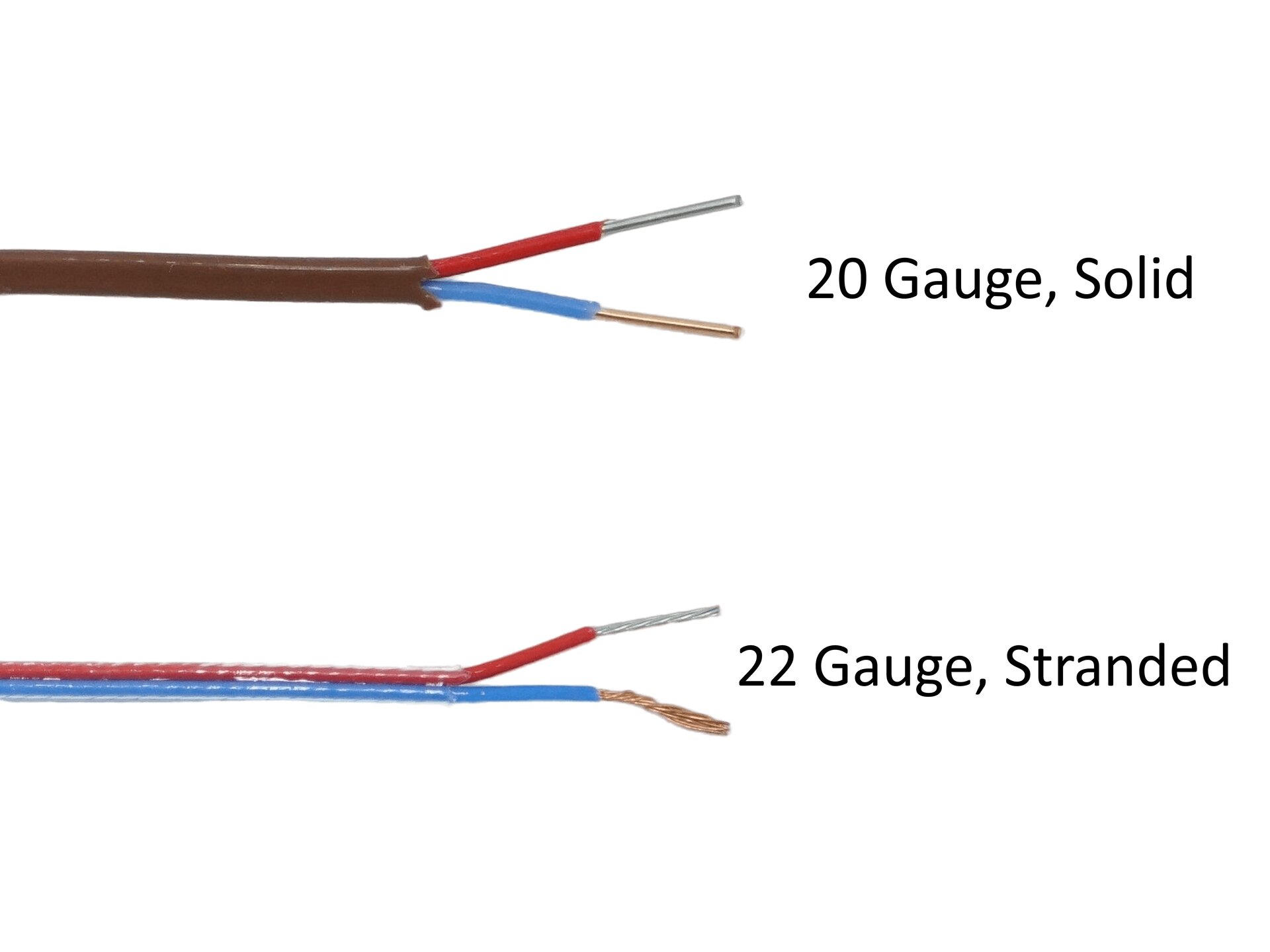
WIRE TYPES
Connectors

(#C6) This connector is attached to the container-end of a heat penetration wire. It has two male plugs (one copper and one constantan) that plug into a thermocouple installed into a container, or a Female Thermocouple Connector (#C7).This is a Non-Locking connector and can be used in most applications (unless a secure connection is required). The non-locking connector works with the Non-Locking Thermocouple Receptacle (#C5), which sits flush against the container. Click here to purchase this connector by itself.

(#C10) This connector is attached to the container-end of a heat penetration wire. It has two male plugs (one copper and one constantan) that plug into a thermocouple installed into a container, or a Female Thermocouple Connector (#C7). This is a Locking connector, which is used when agitation or stress might cause the connector to become disconnected from the thermocouple. A threaded ring is included on this connector that screws onto the external thread on the Locking Thermocouple Receptacle (#C9). Click here to purchase this connector by itself.

(#C7) This connector is attached to the container-end of a heat penetration wire. It has two female outlets (one copper and one constantan) for a Male Thermocouple Connector (Locking or Non Locking) to plug into it. An external thread is included on this connector which allows a male locking connector to screw onto it, but a non-locking connector can plug into it as well. Click here to purchase this connector by itself.

(#SUBMIN-M) This connector is attached to the datalogger-end of a heat penetration wire. The connector has two male plugs (one copper and one constantan) that plug into the CALPlex Datalogger or a Female Subminiature Connector (#SUBMIN-F). Click here to purchase this connector by itself.

(#SUBMIN-F) This connector is attached to the datalogger-end of a heat penetration wire. The connector has two female outlets (one copper and one constantan) that allow for a Male Subminiature Connector (#SUBMIN-M) to plug into it. Click here to purchase this connector by itself.

This is simply the bare end of the wire without a connector installed at the datalogger-end of a heat penetration wire. This allows you to add your own connector, or you may choose to plug the bare wires directly into the CALPlex Datalogger.
Splitting Wires to Prevent CALPlex Water Damage
When testing with a wired data collection system in a water retort, there can sometimes be an issue where the pressure inside the retort forces water through the lead wire insulation, and can even reach the CALPlex (which may affect performance). To eliminate this, we recommend that you cut away the exterior insulation and "split" or separate the red and blue wires from each other. This allows the water to drip out and exit before it reaches the CALPlex. For a video and setp-by-step walkthrough on how to split your wires, click the image below.

Questions?
If you have any questions about how to design or size your heat penetration wires, please contact us at:
Email: [email protected]
PHONE: 504-733-0300


